During the past several years, I have subcontracted my services to engineering companies working on several projects to detect UneXploded Ordinance (UXOs) for the U.S. government. I have both used instruments in the field and processed the data collected by field technicians. Most of the surveys I have worked on have incorporated GPS receivers into the geophysical instruments for data positioning. This has given me a lot of experience to see the advantages, disadvantages, and potential pitfalls of using GPS positioning for geophysical instruments. While the companies I worked for used high quality differential receivers, I began to wonder if a cheaper alternative might be available for the mineral and hydrocarbon exploration industries. Since the United States removed the signal dithering called Selective Availability designed to degrade GPS positioning quality on May 1st, 2000, the opportunity to find an effective and inexpensive positioning system seemed even more likely.
GPS Basics:
Before I progress, I should discuss some basic concepts that will be pertinent to the rest of this paper. Position information is generated by comparing the time difference between the GPS receiver and the various satellites broadcasting fixed signals. These signals can be measured as either code phase or in carrier phase. The code phase signal (C/A) is of long wavelength and can easily be detected but only gives accuracy to several meters (with Selective Availability off). The carrier phase is broadcast as L1 and L2 wavelengths of 19 and 24 cm respectively. Since the code phase is of such long wavelength, it has a unique signature. Since the carrier phases are much shorter they are difficult to resolve and require careful measurement of the phase as well as amplitude. This usually requires measurements of the carrier phase to be measured for several seconds from several satellites. If any interference occurs, a cycle slip occurs which indicates it is impossible to determine the phase.
Position information can be obtained while occupying a fixed position for some length of time (static mode) or while continuously walking with the rover GPS (kinematic mode). If the rover is receiving corrections from a satellite, a beacon, or a radio link to a base station while it is moving the survey is referred to as real time kinematic (RTK). These corrections can be transmitted by a base station receiver, a coast guard beacon, or a satellite that is part of a Wide Area Augmentation System (WAAS). All of these real time corrections can provide centimeter level accuracy, but can also be easily interrupted by forest canopy or by terrain.
Almost all GPS receivers will generate estimates of error for each position the produce. They produce this in two forms: PDOP values and estimates of error. The PDOP error (Position Dilution of Precision) is a measure of how well the observed satellites are distributed through the sky. A lower number indicates a better precision. An estimate of error will indicate what the GPS processor considers to be the potential error of the measurement horizontally and vertically. Usually this error term is given in meters distance on the ground. As an example, if a solution is obtained using four satellites all located to the south, a relatively large PDOP would be given and the estimated N-S position error would be large.
My System:
In the spring of 2002, I assembled a cheap GPS receiver system designed to be effective, light, and adaptable for multiple instruments. I primarily wanted a system capable of continuously logging data for use with magnetometer surveys. However, I also want to be able to store position information for individual stations. Almost all GPS manufacturers have nice software for navigation and data editing/processing but none consider one might want to integrate a second instrument with the GPS. A few geophysical manufacturers have incorporated GPS receivers with their instruments but they all assume the GPS data is always good and merge their data with the GPS position data. I wanted a more versatile system where I could edit/process the GPS data and then merge them with the geophysical data.
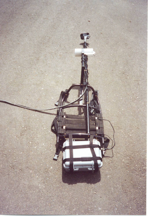
Figure 1 shows the rover GPS unit attached to my magnetometer backpack. The GPS receiver is mounted on the taller rod and the GEM Overhauser magnetometer sensor is white and mounted on the shorter rod. The two cables exiting off the left side of the photograph connect to the magnetometer console mounted on the chest during surveying. The GPS logs data to a personal data assistant (PDA) located in the gray case. A battery to power the PDA and the GPS is also located in it. The case is attached to the backpack using rock climber webbing and buckles. The case is waterproof. I drilled a hole in the side of the case and mounted a locking waterproof connector (built to military specifications) to the side. I have used the system in the field on a production survey and it functioned well (Figure 2).
Figure 1: GPS rover unit mounted on a backpack with a magnetometer. The PDA and battery are located in the gray case hanging below the backpack.
For my system, I decided to use a pair of Garmin GPS35-LVC receivers. These are 12 channel (able to track 12 satellites simultaneously) receivers that record code phase (C/A) information only. The receivers output ASCII data in NMEA format and as binary data in Garmin format. They calculate and output this information every second. The receivers also accept differential correction input from beacons and can be configured by computer using software available for purchase from Garmin. For my PDAs I chose to use HP Jornada 547s. I chose these PDAs because they operate Windows CE/Pocket PC, connect using a COM port, have a lot of memory, and were on sale. I like the Windows CE/Pocket PC operating environment because there are a lot of applications that have been developed for it. I like the COM port connector because most of the PDAs connect via a port from the recharge cradle. The recharge cradles can not be easily used in the field.
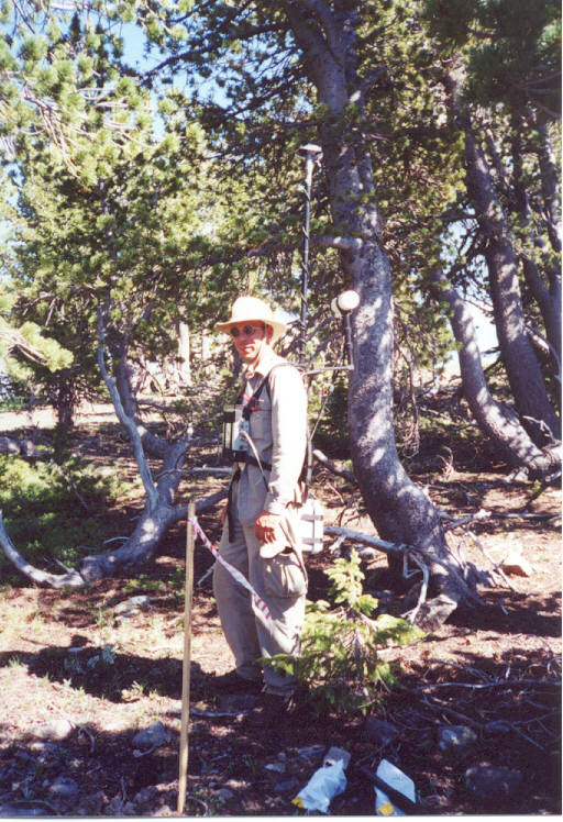
Figure 2: The magnetometer/GPS unit in use on a production survey. The console on the chest logs the magnetometer data and the PDA in the gray case logs the GPS data.
The cost for one receiver system is as follows (all amounts are listed in US Dollars):
GPS receiver $190 PDA data logger $250 Battery $ 60 Waterproof case $ 50 Various connectors $ 70 Logging software $130 Machinist's time $100 Total $850
I have not included the costs of equipment needed to assemble the unit. Almost all of the equipment I had on hand at home such as a hand drill and soldering supplies. I did need to buy two items to complete this project. One was a large diameter drill bit ($26) and the other was a soldering station ($150). My hobbyist soldering iron was not effective at soldering the wires into the pots on the locking connector.
I have an identical system for logging base station information. At the current time, I do not perform differential corrections. I calculate the average position of the base station during the day. Assuming the rover and base GPS are using the same satellites, any wander in the position of the base should also occur in the rover. I subtract these changes from the calculated rover position. The correction is not large, but I like to have a base station GPS so that if any component of the rover fails, I can replace it using the same component from the base.
Survey procedure begins by time synchronizing the magnetometers to the GPS. I do this by using a consumer hand held GPS (Garmin eTrex Venture) and setting it outside for a few minutes so the internal clock can be synchronized to the GPS satellites. I then sync the magnetometer to the GPS time. This procedure allows for an accuracy of 0.5 seconds with a little practice. All magnetometer syncing and survey procedures are done as normal for this type of survey. I start the GPS logging software and put the PDA in the case. I allow the logging program to run the entire day and do not access any of the equipment in the case during the day. At the end of the day, I download the GPS files from the PDAs and to my laptop. These ASCII files can be as large as 12 MB. I also download the magnetometer files and diurnally correct the data. I then merge the GPS files with the magnetometer file using a Fortran program I wrote. The program imports all of the GPS data, performs the base station correction and then imports the magnetometer file. The program searches through the magnetometer file and writes all of the magnetometer data and the GPS data (time, position, PDOP, and estimated error) every time it finds a magnetometer reading with the same time as a GPS reading.
Once I have this file, I import it into a Geosoft Oasis Montaj database. I view the path information and plot the PDOP and estimated error values to a map. This allows me to quickly delete any positions where the PDOP and estimated error values are deemed to be too large. If the errors are very large or no satellites were received for an extended distance, I delete the line segments. These line segments will require resurvey. Once I complete editing, I interpolate position values for all of the magnetometer readings. This is the final data I provide for the client.
Field Tests:
After building my system, I was curious to test it to see how accurate it was. I also wanted to see if I could recognize areas where positioning was poor and how best to edit them. I also wanted to test the accuracy of my system against a simple consumer handheld and a full survey grade differential GPS. I tested the Garmin GPS-35 against a Garmin eTrex Venture and a Leica SR299 dual frequency GPS receiver. Since I am comfortable with the accuracy of my GPS in open, flat terrain, I wanted to test it at a site where I expected to have problems with positioning. For my test site, I selected a forest service trail south of Bozeman.
Figure 3 shows the path I walked while I was wearing the GPS-35 (red) and Leica differential unit (blue) on my backpack. Both GPS antennas were mounted at the same height and only several centimeters apart. The path length is approximately 8.0 km (4 km up the trail and 4 km return distance). The contour interval on the topographic map is 40 feet. The trail follows Middle Cottonwood Creek up a relatively steep canyon with significant timber and brush in the bottom. There were isolated errors of the GPS-35 but in general the path up the trail is very close to the path down the trail. The Leica performed more poorly. There are numerous significant errors of position and for one extended length near the middle of the trail, the receiver completely lost contact with the satellites (exhibited by the straight blue line).
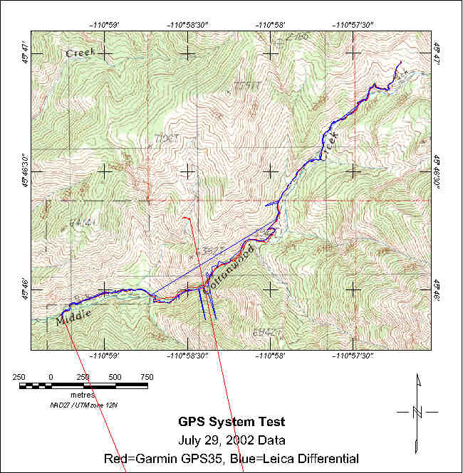
Figure 3: Comparison of the Garmin GPS-35 (red) and Leica differential (blue) units for a test path in the mountains.
In total, I walked the path four times with just the GPS-35, four times with the Venture and the Leica unit, and twice with the Leica and GPS-35. All sensors had times where they would completely lose satellite reception but the Leica had the greatest difficulty. Performance of the GPS-35 and Venture was very similar and I suspect they share the same GPS receiver and processor. I did notice the position of the Venture was much better when it was continuously mounted on the pole as opposed to when I have used it in the past and simply held it in my hand.
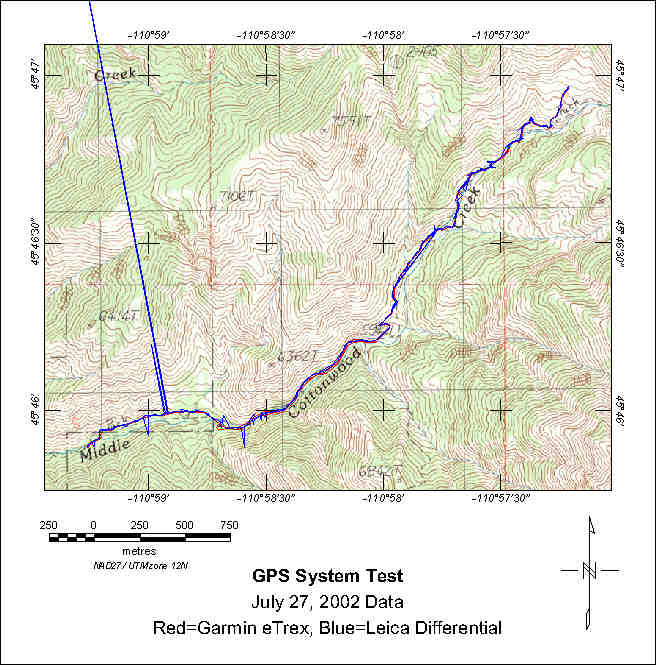
Figure 4: Comparison of the eTrex (red) and the Leica differential (blue) units for the same test path.
Figure 4 shows a comparison of the eTrex (red) response relative to the Leica (blue). Once again the Leica performed poorer than the Garmin unit as exemplified by the numerous deviations of the blue line. A close up of the upper part of the trail (Figure 5) shows where the Leica unit has completely lost lock and more closely shows the deviations of the Leica path.
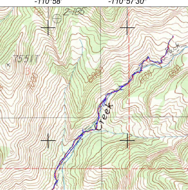
Figure 5: Closeup of the upper portion of the test trail for the eTrex (red) and Leica (blue) comparison.
Figure 6 shows one of the worst errors of position for the GPS-35 unit in a close up of the upper part of the trail. The path is indicated by the red line and individual one second stations are shown by the black dots. For scale, the largest deviation between the path walking up and down the trail is 24 meters. While viewing the error information provided by the GPS (PDOP and estimated error values) is useful, it is also good to look at the path itself. Note the sudden jog in position in the southeastern part of the figure. Also note the loop that is shown in the trail. These are both solid indications the GPS is having trouble finding the position. Another good indicator of poor positioning is given by numerous closely spaced and then several widely spaced positions. This data segment would be a strong candidate for resurvey in a production survey.
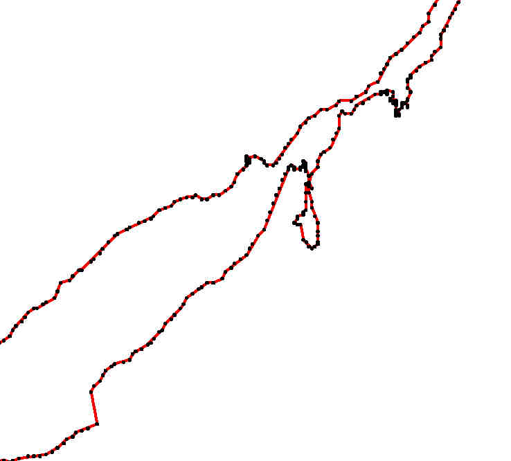
Figure 6: Closeup of the upper portion of the trail for a poor position solution for the GPS-35. Notice the loop and the sudden jog in the lower path.
I suspect the Leica had the greatest difficulty because the processing software for the differential unit is optimized to take advantage of the carrier phase signals. In areas where satellite reception is poor and data are collected in kinematic mode, this causes the differential system to actually perform worse than simple GPS receivers that use the code phase signal. While working on one UXO project where the survey was conducted in flat but heavily timbered terrain, we initially intended to use RTK (real time kinematic) positioning using Trimble 7000 receivers. One base station would broadcast the corrections to the various rovers. Unfortunately the radio link from the base station was only effective for several hundred meters. When we called Trimble tech support they strongly suggested we use the cheaper Trimble Pro XRS receivers instead of the Trimble 7000. They suggested this because the Trimble 7000 software and hardware rely heavily on being able to receive the correction signal to perform processing. While the Pro XRS system could only position us within a few meters, it was still better than the 7000 receivers which couldn't generate any solution.
Potential Problems:
I did have to check for interference between the PDA/GPS system and the magnetometer. Originally, I had the battery mounted on my belt and held the PDA in my hand at waist level. I noted adjusting my hand position added approximately two to three gammas noise to the magnetometer data. Rotating the PDA 90º (i.e. from flat in my hand to vertical in a case attached to my belt) added ten gammas noise! Placing the PDA and battery in the case causes less than one gamma noise. The GPS also originally caused interference to the Overhauser sensor. The GPS pole consists of rod sections 1.5 feet long. If I remove one of those sections of rod (pictured in Figures 1 and 2), the GPS completely overwhelms the magnetometer responses. At the current height, the GPS does not interfere. Before adding any additional EM equipment to a geophysical instrument, one must be careful to check for interference!
The HP Jornada is rated to operate between temperatures of 0 and 40º C (32 and 104º F). This range can probably be increased slightly because of the insulating dead air in the case, but I have not yet tested the extremes.
GPS receivers use two different time systems. These are GPS time and UTC time. UTC time is the Coordinated Universal Time or Grenwich Mean Time. GPS time is the time recorded on the atomic clocks in the satellites. The GPS time presently differs by approximately 12 seconds from UTC time. This occurs because all of the GPS clocks are calibrated to UTC on January 6th, 1980. Every leap year, we gain one day and gain or lose a few seconds. This gain or loss of seconds is not recorded by the GPS clocks. Therefore when one synchronizes his geophysical instrument to the GPS receiver, he must be careful to account for the leap seconds!
Usually when one synchronizes the geophysical clock to the GPS, it is easily possible to obtain 0.5 second accuracy with a little practice. However, I have worked with field techs who have difficulty syncing the units to within TEN seconds of each other. Therefore, it is sometimes useful to perform a lag correction in the field prior to beginning the survey. For a magnetometer survey, I drive three 9" nails into a tree at the sensor height. I then walk a 100 meter north-south line passing the nails at the 50 meter mark. I repeat this line from one to two times, walking in the opposite direction each time. Since the nails don't move, the anomaly they produce should occur in the same location when the magnetometer file is merged with the GPS file. If they don't, I lag the position of magnetic data relative to the time stamp of the GPS until the anomaly peaks from walking the line north and south are coincident.
I had quite a bit of difficulty in the beginning finding a program that can log the GPS data to the PDA. I tried several public domain programs and couldn't get any of them to work. Finally I purchase the CEWedge program. This program also didn't work (it would often lock up and lose data) until I called technical support at TAL Technologies. After a few days of trials, the tech support person was able to personally modify their code and email a new version to me. Also, Microsoft's ActiveSync program that synchronizes data between the PDA and the host computer can also cause problems. Every time one downloads data to the laptop, one has to activate the COM port on the PDA to talk to the laptop. Every time one wants to log data from the GPS, one has to deactivate the PDA-laptop link. If one fails to do this, he will spend the entire day in the field not logging any data to the PDA!
Alternative Setups:
The current system I have works well for collecting kinematic data, but I would prefer to have more functionality. My dream system would allow me to navigate using the GPS, be able to select whether to collect static points or kinematic GPS data, and to be able to differentially correct static data. These enhancements are possible with the system I have but require significant software development and a PDA that is EM radiation clean, resistant to moisture, and resistant to impact.
The Garmin GPS-35LVC does support output of NMEA and binary phase data. There is a program called OziExplorer which accepts NMEA input and will display your track as you walk. It also allows you to import maps in any number of formats so you can guide your own path. Unfortunately OziExplorer does not write the NMEA statements to a file. If a second COM port is available on the PDA, you can log the binary data to a file. Garmin has their output fully documented and there is a public domain code available that will convert Garmin binary data to ASCII RINEX format. The RINEX format is supported by most GPS differential correction software. The RINEX format is also fully documented. It would probably require some editing of the existing conversion code, but it shouldn't be too difficult convert the Garmin data and do the differential corrections using a commercial software package. The software required to log the Garmin files can be written in either QuickBASIC or VisualBASIC. A company called PocketPC has developed software that allows you to run DOS programs such as QuickBASIC on WindowsCE devices. Microsoft has developed a set of widgets as a subset of standard VisualBASIC that allow you to run some VisualBASIC software on PocketPC devices.
There are PDAs that have been developed for use in outdoor environments. These devices are very similar to their commercial counterparts, but have been packaged in "ruggedized" cases that are more resistant to drop impacts and moisture penetration. Unfortunately, the minimum cost of a unit with reasonable protection is approximately US$1000. Also, there is no way to know if one of these devices is EM signal clean until after one has tested it with his field gear. To develop my dream system, I have to invest a significant amount of additional money and spend a lot of time troubleshooting existing software and writing new code.
Summary:
I built this system to be an adaptable, inexpensive, and effective positioning system while I perform geophysical surveys. The GPS I selected only collects code information and options for differential corrections are limited. For kinematic surveys, I do not feel much is gained from the additional expense of a survey grade differential system, or a beacon to receive Coast Guard or WAAS corrections. These differential corrections can certainly be helpful in unforested, flat terrain (accuracy of one meter or better); but in those areas raw code information is also good (accuracy of five meters or better). In places where satellite reception is poor, it is unlikely differential corrections will work or reception from a beacon transmitter or WAAS satellite will be effective. Therefore, I don't think much is gained by using a more expensive system for kinematic surveying. I do believe post processed differential systems can be very effective for static surveys in areas of forest canopy and mountains, however.
I believe GPS positioning offers a cost effective positioning alternative to grid surveying and cutting. Some precautions are necessary for good GPS positioning. GPS works best when the beginning and ends of lines occur in unforested areas. This allows the GPS to calibrate itself. Most errors in position can be edited and interpolated in the field. In the places were extensive data is poor or lost because of poor satellite constellation, resurveying is necessary. I do not recommend using simple position information without error estimates from GPS receivers. If the area is forested or if topography is steep, it is likely significant errors in positioning can occur.
I wrote this paper to pass along information I have learned while setting up my own system. I had to spend quite a bit of time searching for information on various components and assembling them. Hopefully, the reader is now better prepared than I was a few months ago. However, there is still a lot of work and skills required to assemble your own system. Anyone who wants to assemble a system needs to be proficient with hand tools, soldering, and writing code. Also the editing, processing and merging of the GPS positioning information with the geophysical data can be complicated and beyond the skills of many field technicians.
I wrote this paper to disseminate the information I have gained on GPS systems and how to integrate them with geophysical sensors, but I also wrote it to generate work for myself. If you would like to have someone build a GPS system to integrate with a geophysical sensor, or would like to have someone perform a field survey using good GPS positioning capabilities, I would gladly like to offer my services.
Clark Jorgensen
Useful Resources:
The following is a list of sources of information I found helpful. This list and any mention of particular products or manufacturers do not constitute an endorsement by me. I have included these details for definitiveness. The reader may prefer different manufacturers and products.
Garmin International (www.garmin.com): General information on their receivers including the GPS-35LVC, downloadable technical data sheets, and instruction to order the configuration software for the GPS-35 series.
Pelican Cases (www.peliproducts.com): information on various types and sizes of waterproof cases.
OziExplorer (www.oziexplorer.com): CE compatible software for logging data tracks from numerous GPS manufacturers.
CEWedge (www.taltech.com): Data logging software for numerous devices including CE devices.
PocketDOS (www.pocketdos.com): utility that allows you to run all DOS programs on a Pocket PC handheld.
Geosoft Oasis Montaj (www.geosoft.com): Geophysical processing software with powerful utilities for database processing.
Allied Electronics (www.alliedelec.com): Huge catalogue of electrical components including locking connectors typically used on geophysical instruments.
Pen Computing Winter/Spring 2002 issue: The issue is a buyer's guide for PDAs including numerous "ruggedized" PDAs (PDAs placed in hard shells more resistant to water, temperature, and drops).
Coast Guard beacon coverage (www.navcen.uscg.gov/dgps/coverage/default.htm) is shown for all of the fifty states.
Differential data from Garmin receivers (http://artico.lma.fi.upm.es/numerico/miembros/Antonio/async) can be downloaded from this web page. There are numerous warnings that the author gives to tell you he is not responsible for any harm you incur to your system.
OmniSTAR WAAS coverage (www.omnistar.com) is shown for the entire globe as well as annual subscription prices.
Embedded VisualBASIC for handheld devices (www.microsoft.com/mobile/downloads/emvt30.asp) is available for download from Microsoft.